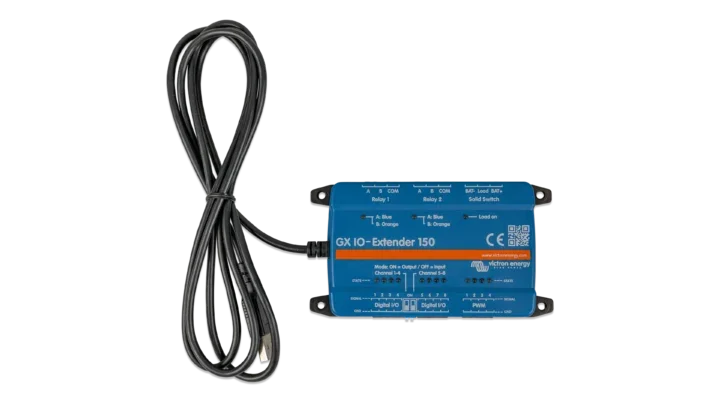
Victron Energy GX IO-Extender 150, GX Device Input/Output Expansion for Relays, Sensors, and More
SKU: BPP900800150
Product Summary
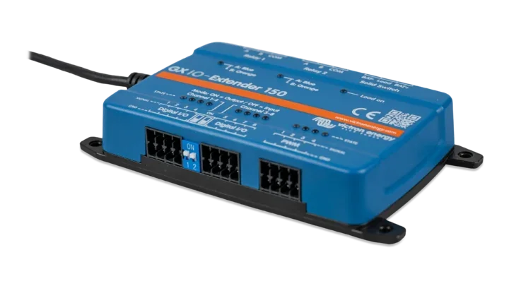
The Victron GX IO-Extender 150 is a USB-powered expansion module that adds digital I/O, PWM outputs, latching relays, and a solid switch to any compatible Victron GX device. Plug it into a Cerbo GX or Ekrano GX and the additional inputs and outputs appear on the system immediately, controllable through Node-RED or the GX user interface.
Specifications:
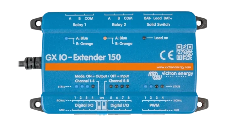
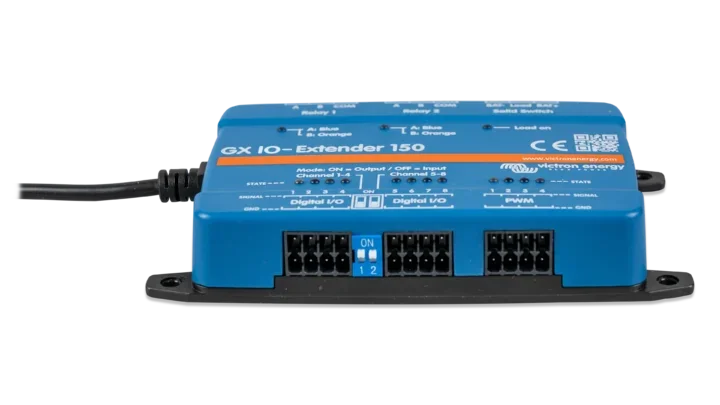
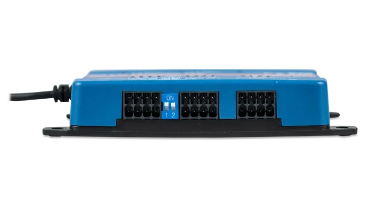
- 8 digital I/Os, configurable as inputs or outputs in two groups of four (DIP switch selectable)
- 4 PWM output channels, 0 to 5V, 8-bit resolution at 1.5625 kHz
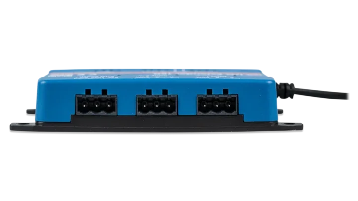
- 2 bistable (latching) relays, DC rated 3A @ 30V / 1A @ 60V / 0.3A @ 220V (90W max)
- 1 solid switch, 70VDC max, 4A max load current
- USB powered, under 100 mW idle, 1W max (under 200 mA at 5V)
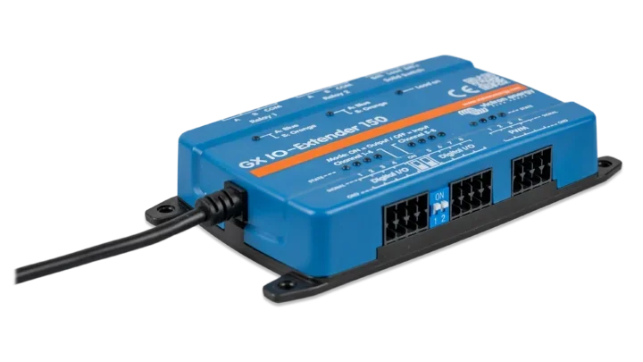
- Pluggable spring terminals for tool-free wiring
- Weight: 0.37lbs
- Dimensions: 4.84×2.64×0.91in
- 5-year Victron warranty
Log in to check member price and detailed stock information.
| Need more than what's available? Tell us what you need and we can source it for you. |

Current Connected is YOUR Victron product specialist
About the Victron GX IO-Extender 150
The GX IO-Extender 150 expands the I/O capabilities of Victron's GX platform. If you have a Cerbo GX or Ekrano GX and need more digital inputs, outputs, relays, or PWM channels than the GX device provides on its own, this module fills that gap. It connects via a single USB cable that also provides power, so there is no separate power supply to wire.
Once connected, all of the IO-Extender's ports show up on the GX device and become available in the Switch pane of the remote console. For advanced automation, the module integrates with Node-RED on Venus OS Large, giving you a low-code programming environment to build custom logic flows.
Digital I/O: 8 Configurable Channels
The eight digital I/O ports are split into two groups of four. Each group is set as either inputs or outputs using a DIP switch on the module, giving you four possible configurations: 8 inputs, 8 outputs, 4 inputs + 4 outputs (either group as either role). Changes to the DIP switches require a power cycle of the device before they take effect.
When configured as inputs, the ports accept 3.8 to 5.5V signals and support several predefined types through the GX interface: pulse meter, door alarm, bilge pump, bilge alarm, burglar alarm, smoke alarm, fire alarm, CO2 alarm, and generator run status. When configured as outputs, the ports deliver 5V at a maximum of 4 mA. That is a signaling-level output only. It is not enough to drive a relay coil directly, so you will need an external transistor or FET driver to switch anything beyond a logic-level signal.
Each port has a blue or orange LED to indicate its current state.
PWM Outputs: 4 Channels for Variable Control
The four PWM output channels produce a 0 to 5V signal at 8-bit resolution (256 steps) with a fixed frequency of 1.5625 kHz. These are useful for LED dimming, fan speed control, motor regulation, or any application where you need proportional control rather than simple on/off switching. Each channel has an LED indicator whose brightness reflects the current PWM duty cycle. The PWM ports connect between GND and signal.
Bistable (Latching) Relays
The two onboard relays are bistable, meaning they hold their position even when the module loses power. This is a different behavior from the monostable relays on the Cerbo GX, which return to a default state when power is removed. The latching design uses a short pulse to switch between position A and position B, consuming no power to maintain either state. A blue LED indicates position A and an orange LED indicates position B.
Each relay has a COM (common), A, and B terminal. In toggle mode, you can switch a load between two circuits or mimic a traditional normally open relay by wiring the load to one terminal and leaving the other disconnected. A momentary mode is also available, where the relay briefly switches and then returns to its resting position. This is useful for triggering alarms, sirens, or other pulse-activated devices.
Contact ratings for resistive loads: 3A at 30VDC, 1A at 60VDC, 0.3A at 220VDC (90W max). On the AC side: 2A at 60VAC, 1A at 125VAC, 0.5A at 250VAC (125VA max).
Solid Switch for DC Loads
The solid switch is an electronic (no mechanical contacts) high-side DC switch with Bat+, Load, and Bat- terminals. It supports up to 70VDC and 4A of load current, making it suitable for switching contactors, indicator lights, or other low-current DC devices. Capacitive and inductive load limits vary by voltage and current, so check the ratings if you are switching anything with a significant inrush or back-EMF characteristic.
Like the relays, the solid switch supports both toggle and momentary modes through the GX interface or Node-RED.
Signaling Device, Not a Load Switch
Victron is clear that the IO-Extender 150 is designed for signaling and control, not general load switching. The relay and solid switch current ratings are low by design. If you need to switch larger loads (lighting circuits, pumps, heaters), use the IO-Extender's outputs to trigger an external contactor or relay module rated for the load.
Installation
Mount the module to a wall or DIN rail (DIN rail adapter sold separately). Connect the included USB cable to an available USB port on your GX device. On some Cerbo GX models, the USB port closest to the HDMI port may not work for this purpose, so check your Cerbo GX manual for port compatibility. All wiring connections use pluggable spring terminals, so no special tools are required.
For Node-RED functionality, your GX device must be running the Venus OS Large firmware image with Node-RED enabled. Not all GX devices support Venus OS Large. Refer to Victron's Venus OS Large documentation to confirm compatibility with your specific GX hardware.
The module operates in ambient temperatures from -20°C to +50°C.
Recommended Accessories


Frequently Asked Questions
Yes. Multiple IO-Extenders can be connected via USB to add more I/O channels to the same GX system.
Yes. The relays, digital I/Os, and PWM outputs are accessible through the Switch pane in the GX device's remote console without Node-RED. Node-RED adds the ability to build custom automation logic, but it is not required for basic control.
The two latching (bistable) relays hold their last position when power is lost. They do not reset to a default state. The solid switch will turn off when power is removed.
No. The digital outputs provide 5V at a maximum of 4 mA, which is a logic-level signal only. You will need an external transistor, FET, or relay driver circuit to switch a standard 12V relay coil.
The IO-Extender works with all GX devices at the hardware level, but Node-RED (which provides the most useful control interface) is only supported on GX devices that run Venus OS Large. The Venus GX and Color Control GX have limited processing power and may not support Venus OS Large. Check Victron's compatibility documentation for your specific device.
Customer Reviews
No reviews yet. Be the first to review this product!