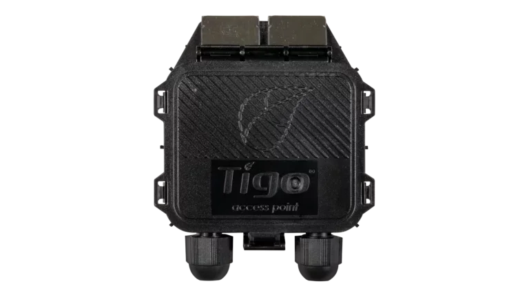
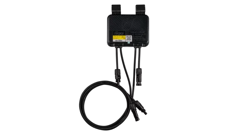
About the Tigo Access Point
The TAP is the wireless bridge in a Tigo monitoring system. It mounts at the array, communicates wirelessly with nearby TS4 units, and sends that data over a wired RS485 connection to the CCA. The CCA then handles internet connectivity and uploads to the Tigo Energy Intelligence platform. Without a TAP, the CCA cannot see TS4 data, since the CCA does not communicate with TS4 units directly.
Mesh Networking and Range
The TAP uses mesh radio communication. Each TS4 unit on the array also acts as a signal repeater, so data hops from module to module back to the TAP. As long as TS4 units are within 10m (33 ft) of each other, the total signal range from the farthest module back to the TAP can extend up to 35m (115 ft). For most residential arrays, a single TAP centrally located on the array covers every panel. Larger arrays, split arrays across multiple roof faces, or arrays with physical obstructions between sections may require additional TAPs.
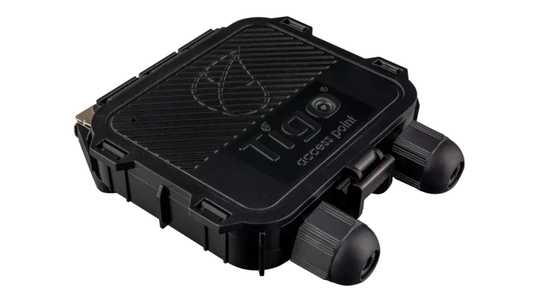
Mounting and Placement
The TAP snaps onto the side of any standard PV module frame using its built-in clips, no tools required. For frameless modules or rail-mounted arrays, the clips remove and the TAP attaches directly to the rail. Mount the TAP near the center of the array with the label facing outward, away from the module. Do not mount the TAP inside an attic. Roofing materials, insulation, sheathing, and shingles block the radio signal and will prevent communication with the TS4 units below.
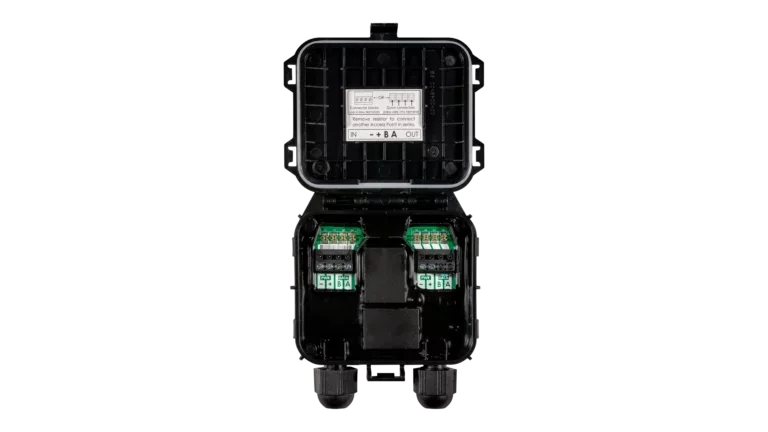
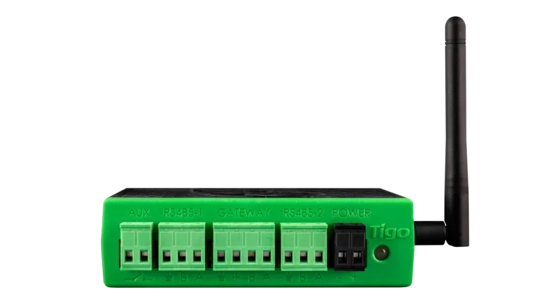
Multi-TAP Wiring
When more than one TAP is needed, TAPs are daisy-chained in series with RS485 cable from the CCA's gateway terminal to the first TAP, then from each TAP to the next. Each TAP includes a pre-installed 120Ω terminating resistor. Remove the resistor from intermediate TAPs and leave it in place at the last TAP in the chain. The required cable is a twisted-pair RS485 cable, sold separately. If the cable will run in the same conduit as inverter DC homeruns, use a cable rated for the corresponding DC voltage per NEC 300.3(C).